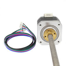
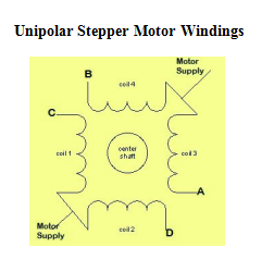
UNIPOLAR STEPPER MOTOR
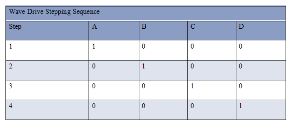
Wave Drive:
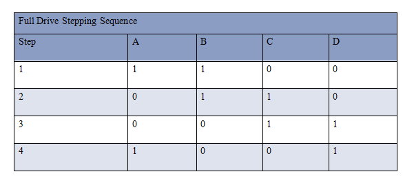
Full Drive:
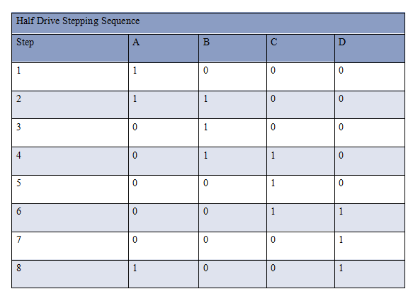
Half Drive:
Bipolar Stepper Motor

Applications
/*  Name     : main.c
 *  Purpose  : Source code for UNIPOLAR FULL STEP DRIVE STEPPER MOTOR Interfacing with ARM LPC1248.
 *  Author   : Gemicates
 *  Date     : 2018-03-02
 *  Website  : www.gemicates.org
 *  Revision : None
 */
#include <LPC214X.H>                             // header file for LPC21XX series

void delay( unsigned int value )                 // delay function declaration
{
unsigned int i,j;                                // This function produces a delay in msec
for(i=0;i<value;i++)
for(j=0;j<5000;j++);
}

int main()                                       // main function
{
unsigned char i;
IODIR0 =0x0000000F;
while(1)
{
for(i=0;i<1;i++)                                 // clockwise rotation
{
IOCLR0=0x0000000F;
IOSET0=0x00000003;
delay(1000);
IOCLR0=0x0000000F;
IOSET0=0x00000006;
delay(1000);
IOCLR0=0x0000000F;
IOSET0=0x0000000C;
delay(1000);
IOCLR0=0x0000000F;
IOSET0=0x00000009;
delay(1000);
}
for(i=0;i<1;i++)                                 // ANTIClock wise rotation
{
IOCLR0=0x0000000F;
IOSET0=0x00000009;
delay(1000);
IOCLR0=0x0000000F;
IOSET0=0x0000000C;
delay(1000);
IOCLR0=0x0000000F;
IOSET0=0x00000006;
delay(1000);
IOCLR0=0x0000000F;
IOSET0=0x00000003;
delay(1000);
}
}
}
/*  Name     : main.c
 *  Purpose  : Source code for UNIPOLAR HALF STEP DRIVE STEPPER MOTOR Interfacing with ARM LPC1248.
 *  Author   : Gemicates
 *  Date     : 2018-03-02
 *  Website  : www.gemicates.org
 *  Revision : None
 */
#include <LPC214X.H>                           // header file for LPC21XX series

void delay( unsigned int value )               // delay function declaration
{
unsigned int i,j;                              // This function produces a delay in msec
for(i=0;i<value;i++)
for(j=0;j<5000;j++);
}

int main()                                     // main function
{
unsigned char i;
IODIR0 =0x0000000F;
while(1)
{
for(i=0;i<1;i++)                               // clockwise rotation
{
IOCLR0=0x0000000F;
IOSET0=0x00000009;
delay(1000);
IOCLR0=0x0000000F;
IOSET0=0x00000001;
delay(1000);
IOCLR0=0x0000000F;
IOSET0=0x00000003;
delay(1000);
IOCLR0=0x0000000F;
IOSET0=0x00000002;
delay(1000);
IOCLR0=0x0000000F;
IOSET0=0x00000006;
delay(1000);
IOCLR0=0x0000000F;
IOSET0=0x00000004;
delay(1000);
IOCLR0=0x0000000F;
IOSET0=0x0000000C;
delay(1000);
IOCLR0=0x0000000F;
IOSET0=0x00000008;
delay(1000);
}
for(i=0;i<1;i++)                                // ANTIClock wise rotation
{
IOCLR0=0x0000000F;
IOSET0=0x00000008;
delay(1000);
IOCLR0=0x0000000F;
IOSET0=0x0000000C;
delay(1000);
IOCLR0=0x0000000F;
IOSET0=0x00000004;
delay(1000);
IOCLR0=0x0000000F;
IOSET0=0x00000006;
delay(1000);
IOCLR0=0x0000000F;
IOSET0=0x00000002;
delay(1000);
IOCLR0=0x0000000F;
IOSET0=0x00000003;
delay(1000);
IOCLR0=0x0000000F;
IOSET0=0x00000001;
delay(1000);
IOCLR0=0x0000000F;
IOSET0=0x00000009;
delay(1000);
}
}
}
/*  Name     : main.c
 *  Purpose  : Source code for UNIPOLAR WAVE DRIVE STEPER MOTOR Interfacing with ARM LPC1248.
 *  Author   : Gemicates
 *  Date     : 2018-03-02
 *  Website  : www.gemicates.org
 *  Revision : None
 */
#include <LPC214X.H>                            // header file for LPC21XX series

void delay( unsigned int value )                // delay function declaration
{
unsigned int i,j;                               // This function produces a delay in msec
for(i=0;i<value;i++)
for(j=0;j<5000;j++);
}

int main()                                      // main function
{
unsigned char i;
IODIR0 =0x0000000F;
while(1)
{
for(i=0;i<1;i++)                                // clockwise rotation
{
IOCLR0=0x0000000F;
IOSET0=0x00000001;
delay(1000);
IOCLR0=0x0000000F;
IOSET0=0x00000002;
delay(1000);
IOCLR0=0x0000000F;
IOSET0=0x00000004;
delay(1000);
IOCLR0=0x0000000F;
IOSET0=0x00000008;
delay(1000);
}
for(i=0;i<1;i++)                               // ANTIClock wise rotation
{
IOCLR0=0x0000000F;
IOSET0=0x00000008;
delay(1000);
IOCLR0=0x0000000F;
IOSET0=0x00000004;
delay(1000);
IOCLR0=0x0000000F;
IOSET0=0x00000002;
delay(1000);
IOCLR0=0x0000000F;
IOSET0=0x00000001;
delay(1000);
}
}
}
/*  Name     : main.c
 *  Purpose  : Source code for BIPOLAR STEPPER MOTOR Interfacing with ARM LPC1248.
 *  Author   : Gemicates
 *  Date     : 2018-03-02
 *  Website  : www.gemicates.org
 *  Revision : None
 */
#include <LPC214X.H>                                       // header file for LPC21XX series

void delay( unsigned int value )                           // delay function declaration
{
unsigned int i,j;                                          // This function produces a delay in msec
for(i=0;i<value;i++)
for(j=0;j<5000;j++);
}

int main()                                                 // main function
{
unsigned char i;
IODIR0 =0x0000000F;
while(1)
{
for(i=0;i<1;i++)                                           // clockwise rotation
{
IOCLR0=0x0000000F;
IOSET0=0x00000008;
delay(1000);
IOCLR0=0x0000000F;
IOSET0=0x00000002;
delay(1000);
IOCLR0=0x0000000F;
IOSET0=0x00000004;
delay(1000);
IOCLR0=0x0000000F;
IOSET0=0x00000001;
delay(1000);
}
for(i=0;i<1;i++)                                          // ANTIClock wise rotation
{
IOCLR0=0x0000000F;
IOSET0=0x00000001;
delay(1000);
IOCLR0=0x0000000F;
IOSET0=0x00000004;
delay(1000);
IOCLR0=0x0000000F;
IOSET0=0x00000002;
delay(1000);
IOCLR0=0x0000000F;
IOSET0=0x00000008;
delay(1000);
}
}
}